Digital Temperature Sensor - Solution Alpha
Description
This solution uses a micro-USB port to power the board. Only the power pins from USB are used, so most phone chargers should be able to be used as power sources. In soldering this together, I learned that micro USB ports are difficult to solder by hand. I accidently shorted 5 V to one of the data lines, which causes problems with some phone chargers.
3 power rails exist on this board: 5V, 3.3V, and LED_VCC. The first is raw from off-board, the second is used to power the microcontroller (and other IC's), and the third is of course for the eight LED's. The first two are needed in my eyes (5V is what USB always provides, but I'd rather not use off-board voltage straight, if I'm going to use a voltage regulator I may as well drop the voltage to 3.3V) but the LED_VCC rail is the result of my voltage-control approach to the LED's rather than a current-control approach. Retrospectively, I could've made a better choice, as an LED's brightness is directly analog to its current, which should have a predictable relationship with its voltage dropped across, but in practice that relationship can vary slightly between parts.
To communicate between the microcontroller, the temperature sensor, and the LED driver, I2C was used because of its simplicity.
Relevant Images
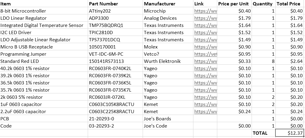
BOM

Schematic

